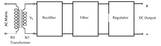
we have studied about the operation and V-I characteristics of a PN junction diode in the previous lesion. We have also seen that the diode can conduct only when it is forward biased and blocks when it is reversed biased. This property of the diode makes it essential components of DC power supplies which are used to power electronic systems and circuits. The block diagram of typical DC power supply is mention below:
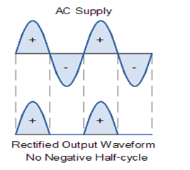
“The process of converting A.C (alternating current) to D.C (direct current) is called rectification”.
The transformer is used to step down the A.C (250V, 50/60 Hz) to desired voltage level by controlling the turn ration N2:N1. This secondary voltage, Vs is 230V (N2:N1). The transformer also provides electrical isolation to the electronic system from AC mains.
The rectifier converts the A.C voltage to pulsating D.C, which is smoothed by filter circuit. The output voltage of the power supply is expected remain constant against variation in the load current or variation in input voltage. This is accomplished by using a suitable voltage regulator.
There are different types of rectifiers and filters are as under follow :
Half Wave Rectifiers:
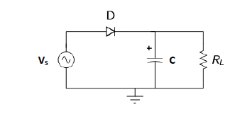
The half is simplest rectifier that uses a single diode and a load resistor as shown in the circuit diagram below:
The diode is forward biased during each positive half cycle causing to flow in the circuit. These current results in voltage Vout across the resistor RL

The wave waveform of Vout with respect to Vs is shown below

The output voltage is pulsating DC which has a significant AC component and DC components which is the average value of Vout. This kind of voltage is not suitable as a DC supply. A simple way to make the output voltage is to connect a filter capacitor across the output.

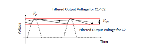
During positive half cycle as Vs increase, the diode D conducts allowing the capacitor to charge to peak voltage of the sinusoid. After the peak voltage Vs starts decreasing making the anode of the diode at lesser voltage than cathode as the capacitor C holds the voltage at cathode at the peak voltage. Thos reverse biases the diode D and the capacitor C start discharging through RL till the voltage across ( which is the voltage at the cathode) it becomes less than Vs which is rising sinusoid. The diode then gets forward biased and start conducting till the peak reached and this cycle continue. The charging and discharging of the capacitor cause ripple factor in the output. Larger capacitor results slow discharge and “flat” output giving rise to less ripple content.
Ripple factor of half wave rectifier :
Ripple factor is a measure of effectiveness of a rectifier circuit. Its id defined as the ratio of RMS value if the AC components ( ripple components) Irms in the output waveform to the DC component VDC in the output waveform.
The value of ripple factor of single phase half wave rectifier is equal to 1.21. Since, ripple factor is the ratio of rms value of fluctuating ac component to the average voltage or dc value. Its value of 1.21 means that, the ac fluctuating component in the rectified output of half wave rectifier is 121% of the expected DC output or average vale. This simply means, the rectification is poor as the ripple content is even higher than the DC output. Let us now see the calculation of this ripple factor.
The circuit diagram of single phase half wave rectifier is shown below.
The output waveform of half wave rectifier ignoring cut-in voltage is shown in figure below. Blue color depicts the supply voltage whereas red color denotes the rectifier output current.
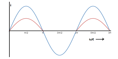
This output current can be defined as
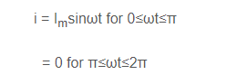
Let us now find the rms value and average value of this current to find the ripple factor of half wave rectifier.
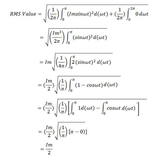
Thus, the rms value of current output of half wave rectifier is 0.5 times of the peak current i.e. 0.5Im.
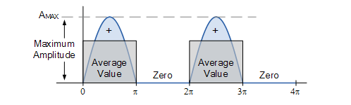
The average value of single phase half wave rectifier is equal to 0.318 times of peak current i.e. 0.318Im
Let us consider a sinusoidal current i = ImSinωt as shown in the figure below. We will calculate its avg. value for one time period ωt = 2π from the definition of average value of alternating current.
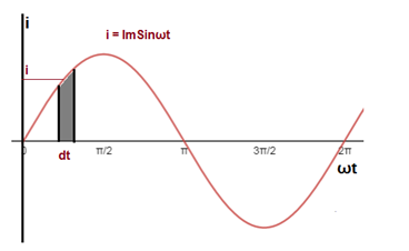
we need to find the charge transferred by this AC current for time t = (2π /ω). For this, let us consider a infinitesimally small time interval dt where the value of current is i .
The charge transferred by this assumed current i in this time dt is given as

Now, we will integrate this for the entire time period i.e. from ωt = 0 to 2π to get the total charge transferred in one time period.
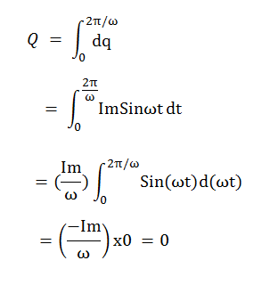
Thus, the charge transferred by AC current for one time period is zero. Therefore, its average value is zero. This can also be explained in other way. Since the positive and negative half cycles are equal, therefore the charge transferred due to these two halves will be equal but in opposite direction. Therefore, net charge transferred across any point of circuit in one time period of sinusoidal AC current is zero. Hence, its average value is zero. For this reason, average value of sinusoidal AC current or voltage is defined and calculated for half cycle i.e. for t= (π/ω). Let us now calculate this.
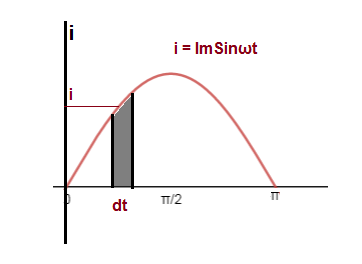
Charge Transferred across any point of circuit for half cycle is given as below.

Thus the charge transferred by half cycle of Sinusoidal AC current = (2Im/ω).
If Iavg being the average value, then this current must also transfer the same charge for t = (π/ω).Since average value is the DC value, this charge will be equal to Q = Iavgx(π/ω).
Thus,
Iavgx(π/ω) = (2Im/ω)
Iavg = (2Im / π)
= 0.637Im
The average value of AC sinusoidal current or voltage is equal to 0.637 times of its peak value. Now, the ripple factor of half wave rectifier can easily be calculated from the formula
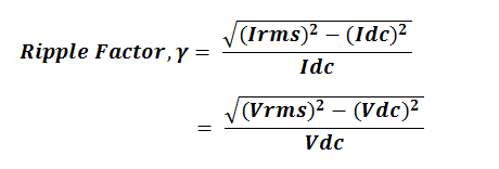
Putting the value of rms current and average current, the value of ripple factor can easily be calculated from the above formula.

Thus, the value of ripple factor of half wave rectifier is 1.21.
We can measure the value of RMS component of overall output waveform form which we can estimate the value of Irms.

For half wave rectifier,

This lead to ripple factor r=1.21 for half wave rectifier.
The ripple factor can be significantly reduced using a filter capacitor.
For a half wave rectifier with filter capacitor, ripple factor is given by,

Where f is the frequency of pulsating DC in this case as that of A.C mains.
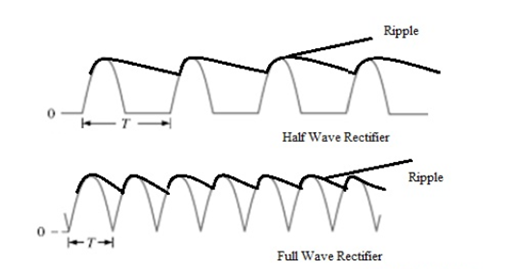
The value of ripple factor can be estimated form the waveform of the output voltage.
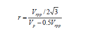
Where Vp is the peak value of the output and Vrpp is the peak of the ripple voltage.