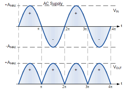
A full wave rectifier that utilize the both +ve and –ve half of the input cycle and undergoes rectification is defined as a full wave rectifier. The average value of the output is the higher in the full wave rectifier compare to that of a half wave rectifier. The number of ripples is less in the F.W.R and produced smooth O/P.
In a full wave rectifier, the two cycle of the supply are rectified. To implement this technique basic full wave rectifier require two diodes. Each diode is utilize during each cycle. When the +ve cycle is applied one diode conduct and during a negative cycle, the other diode tends to conduct.

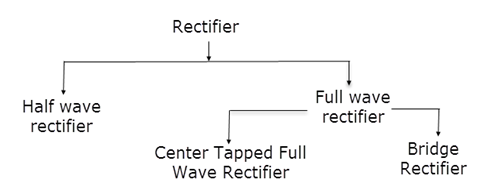
Types of full wave rectifier :
There are three types of full wave rectifier are as under follow:
- Full wave rectifier with centre tapped transformer.
- Full wave bridge rectifier.
Precision full wave rectifier :
Full wave rectifier with centre tapped transformer :-
The centre tapped full wave rectifier circuit consists of two diodes , a transformer and a resistive load. A centre tapped transformer is a normal transformer that has a slight modification in it. Its secondary winding has a wire connected at the centre. Hence, the input AC supply while passing through the secondary winding its voltage is divided into two half. The one half is referred to +ve half voltage and other one is –ve half.
The circuit consists of two diodes that are connected in II to each other along with the resistive load. The load is connected at the centre tapped wire of the secondary winding.
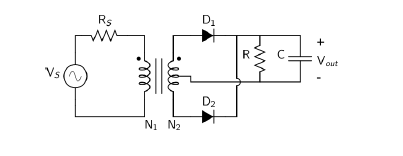
The circuit consists of a center-tapped transformer, followed by the rectifier formed by two diodes D1 and D2, and finally the load R with a capacitor filter C. The circuit is designed such that the current through the load is always in the same direction during both the half cycles. Assume that the capacitor is not connected initially. Due to the center tap rectifier, during the positive half cycle of the input Vs, A is positive with respect to B, hence diode D1 will be forward biased and D2 will be reverse biased. This results in the current flowing from A-D1-R-B-A. In negative half cycle, C is positive with respect to B. This makes C positive with respect to B causing diode D2 to get forward biased making the current flow from C-D2-R-B-C. Thus in both the half cycles the current through R flows in the same direction resulting in pulsating DC across R.

During the positive half cycle, capacitor C will charge to the peak of the input waveform while the load R is being supplied current through D1. When the input starts to go below its peak value, the voltage across C will cause D1 to be reverse biased, thus disconnecting the rectifier from the load. The capacitor will then provide the necessary current for the load. The rate of potential drop across C will be based on the values of R & C.
During the negative half cycle, diode D2 will initially be reverse biased due to voltage across C. When the voltage at the input crosses the dropping voltage across C, D2 will be forward biased. Now the load is supplied current by the input while simultaneously charging C. This continues till the negative peak of the input waveform, after which D2 will be reverse biased. The next positive cycle is similar to the previous negative cycle with diode D1 being forward biased when the input voltage crosses the voltage across C. Capacitor C ensures that the voltage across load R remains close to the peak of the input voltage.
Full wave Bridge rectifier:
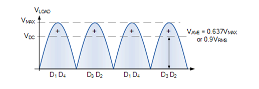
The four diodes connected in a bridge form. The technique used here is that the diagonally opposite diodes conduct during one half of the cycle and during the second half the remaining two diode conducts. Hence this basic model is simple to construct compare to that of any other rectifier circuit. The circuit uses four diodes D1, D2, D3 and D4 connected in the form of bridge.
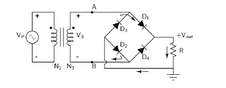
During the positive cycle of Vs, point A is positive with respect to B causing diode D1 and D2 to forward bias and D3 and D4 to get reversed biased. This results in the current to flow from A, through D1, R, D2, B to A.
During negative cycle, the polarities change. Now point B is positive with respect to A causing diodes D3 and D4 to conduct and D1 and D2 to reverse bias. The resulting current then flows from B through D4, R, D3, A to B. In both the cycles, the current through the load resistor R flows in the same direction ensuring the pulsating DC across R in both the half cycles of the input voltage. Hence, this is a full wave rectifier.
The output voltage can be smoothened by connecting a suitable capacitor across the load resistor as explained in section B.
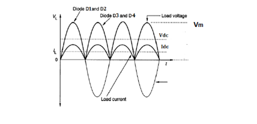
The ripple factor of full wave rectifier ( both centre tapped and bridge rectifier).
The ripple factor is given by
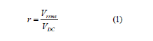
Where Vrms is the RMS of A.C components(ripple) in the rectifier output and VDC is the D.C component (Average value) of the rectified output.
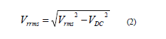
Where Vrms is the RMS value of the rectified output
For full wave rectifier,
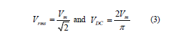
Where Vm is the peak of the voltage Vs . Substituting these values in (2) we get.

This is a significant improvement in the ripple factor compared to that of a Half wave rectifier (r=1.21). However, this pulsating DC is not useful to power electronic circuits as it still has a large AC component. The output can be made smooth by using capacitor filter as described in Half Wave rectifier.
The ripple factor for full wave rectifier with capacitor filter is given by.
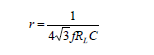
Where f is the frequency of the signal Vs
Precision Full wave rectifier:
It is a type of rectifier that consists of super diodes and mainly its configuration is based on operational amplifiers (opamps) so that its characteristics resemble ideal of the diode and also rectifier. During high precision signal processing, it is proven to be beneficial. In the normal rectifiers that have ordinary semiconductor devices as basic pieces of equipment can lead to the voltage drop. This can be overcome by using precision rectifiers.
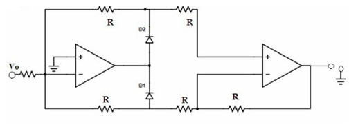
In the precision full-wave rectifiers, it considers both positive and the negative halves of the cycle. But either the output generated is completely inverted or non-inverted. When the operation is performed on the precision rectifier the output generated as considered positive full-wave rectifier can be given as

The output generated for the negative full-wave rectifier can be given as

Advantages
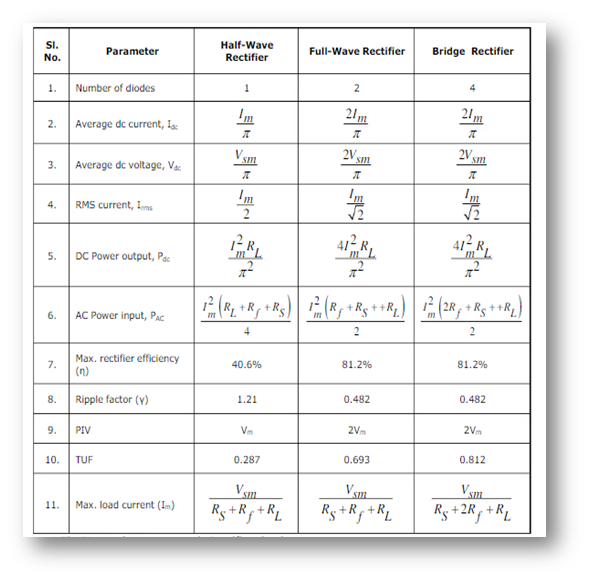
- The full-wave rectifier has more efficiency compared to that of a half-wave rectifier.
- There is the utilization of both the cycles. Hence there is no loss in the output power.
- As both the cycles used in rectification. There will be no loss in the input voltage signal.
- Ripple factor is less compared to that of the half-wave rectifier.
- Greater mean in DC value is achieved.
- Compare to the center-tapped full-wave rectifier, bridge rectifier is cost-effective because the center-tapped is more costly.
Applications
- The amplitude for the modulating radio signal is detected using the full-wave bridge rectifier circuit.
- In electric wielding to supply steady DC voltage in a polarized way, this circuit is preferred.
- As the efficiency of rectification is high in this rectifier circuit, it is used in various appliances as a part of the power supply unit.
- It has the capability of converting high AC voltage to low DC value.
In case of powering up of the devices like motors and LED devices these are used.
half-wave rectifier, the diode is forward biased only for short period of time and conducts only during this time interval to charge the filter capacitance. The instant at which the diode gets forward biased, the capacitor instantaneously acts as short circuit and a surge current.